Remote control car base on MCS 51
1.Circuit Design
Before you start, determine the components to use.
Try to select the components that control the trolley.
As the title:
Main control chip:AT89C52 chip
A toy car(which have two motor.The front motor controls the left and right, and the rear motor controls the front and rear)
A chip or module that controls a motor:L298/L9110
Wireless module:NRF24L01(If you like, you can use ESP8266 networking control or HC05 Bluetooth control)
Drop-Out Voltage-Regulator module:5V to 3.3V(The voltage used in NRF24L01 is 3.3V)
The next step is to draw circuit diagram
You can use your hand or some software to draw, this step is to know what you want.
- The minimum system is the core of the hardware circuit design.Because of this you should design the minimum system first.
- And then design the switch and power .With the power and switch single chip microcomputer can work.
- In China you can not only buy components by using TaoBao, but also use it to see some reference details of the components. For example, the control motor chip on this article, you can see the reference details below Taobao
such as:How does L298 work and so on. In this step you can figure out how the components work - Next is to connect the chips and modles with the single chip microcomputer.
- Tips: Remember to reserve the port to upload the code.Otherwise, it's a headache if you don't keep the port to upload you have to remove the chip to upload it everytime. You can use a IDC connector(such as 10pin X9555WV-2X05-6TV01) and a USB TO RS232/485/TTLto upload your code.
After completing the above steps, you can start drawing PCB
Draw PCB according to your own circuit diagram.(I use DXP to draw PCB)
Of course, DXP provides a tool that can draw circuit schematic diagrams.You can use it directly to draw the schematic diagram and the schematic library.
After painting, remember to check whether the connection is connected, etc
Proofing
Send the design drawings to the factory, and the factory will help you proofing.
After welding,then you can debug.
2.Code debug
Complete the above design
You can simulation in protues before you upload the code in the chip.
This method can simulate the running state of hardware under real conditions.
The first thing to do is to let the car move.
- When the trolley moves, first prove that the trolley motor is OK, and then there can be a later control activity.
- If the car can't move, check the problem maybe the motor problem , maybe the L298 problem or some problems with the circuit board be good at using multimeter at this time.
- The motor test is very simple. Connect it with a battery to see if it will move.(It is better to connect a resistor in series. In case of excessive current, the motor may burn during the detection process。)
- Other part use a multimeter to check whether there is electricity or not 。
The next step is to debug the control code
NRF24L01 is used to control in the design, so pay attention to the voltage
The voltage of 51 single chip microcomputer is 5V, and this module is 3.3V
If the module burns out, it is impossible to control it。
Assuming that the computer controls, the computer is the information sending end and the single chip microcomputer is the information receiving end
Single control first(such as go forward, P2.0 port is 0, P2.1 port is 1, and the single chip microcomputer receives the signal "1")
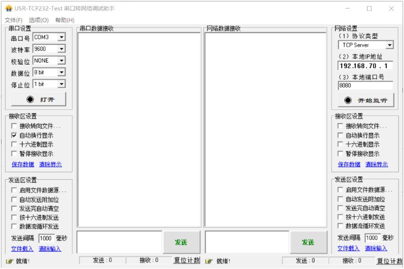
In the computer, use the serial port debugging assistant to send the signal of 1
Key code examples of single chip microcomputer
    if(	rece_buf[1]=='1') 	 		//After the first bit is the received command data, rece_buf[0] is the length of data bits.

                {
                  M0=0;                        //sbit M0 = P2^0   sbit M1 = P2^1
                  M1=1;
                }
Proceed to the next step after successful debugging
Reverse, stop, left turn and right turn control are completed in the same way.Then implementation the project.