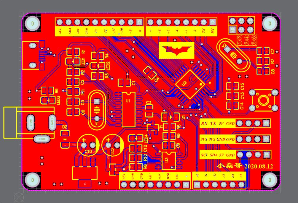
Draws Arduino with AD, including schematic diagram and challenge I met
I use Altium Designer15.
Drawing is the Arduino uno board.
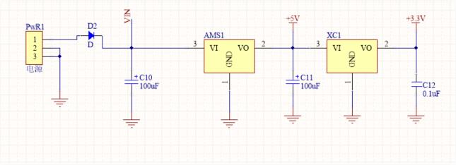
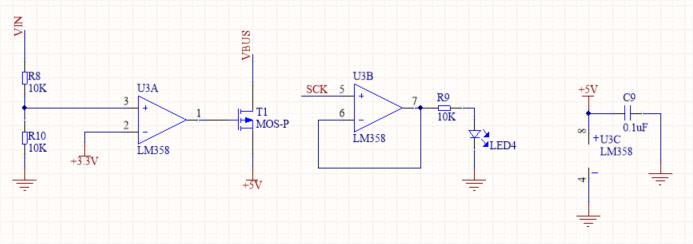
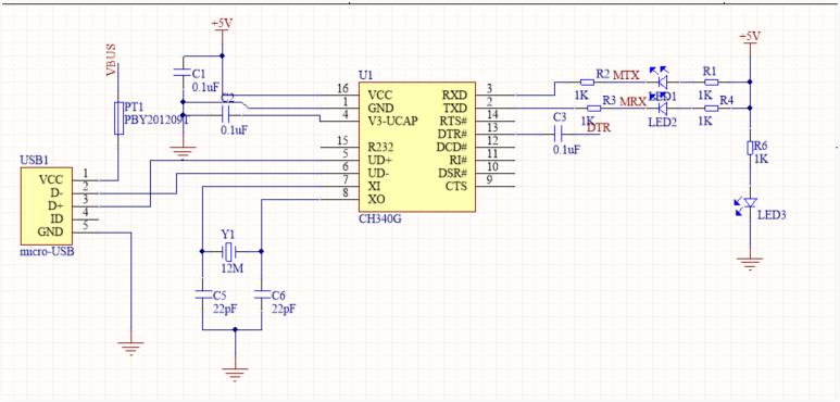
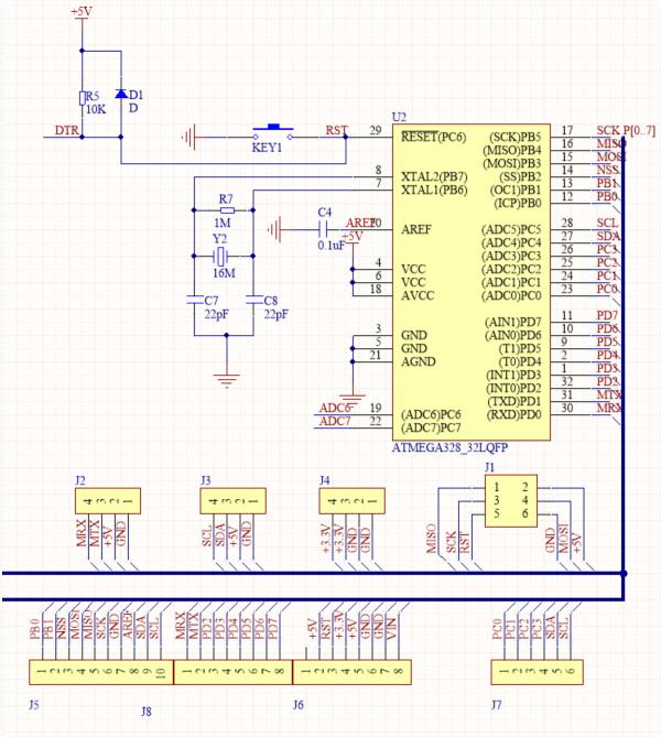
Including four part circuits(Power supply circuit, Comparison circuit, USB Download circuit and AVR single chip microcomputer circuit)
The comparison circuit is the most interesting part I think. Compare the USB power supply with DC power supply through lm358, and select the power side.
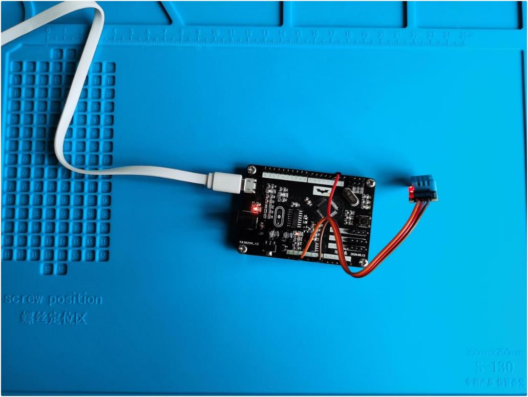
Because there happened to be a DHT11 temperature and humidity sensor nearby, I decided to write a small code to test it.
#include <dht11.h>//Temperature and humidity head file. You have to download this head file
#define DHT11PIN 2 //D2 is defined as the data output port
dht11 DHT11;
void setup() {
// put your setup code here, to run once:
Serial.begin(9600);//Define baud rate
pinMode(DHT11PIN,OUTPUT); //Set D2 as data output
}
void loop() {
// put your main code here, to run repeatedly:
temp = analogRead(Aout); //Read analog data of A0 pin
String a=String(temp);
int chk = DHT11.read(DHT11PIN); //Assign the read value to chk
int tem=(float)DHT11.temperature; //Assign the temperature value to tem
int hum=(float)DHT11.humidity; //Assign humidity value to hum
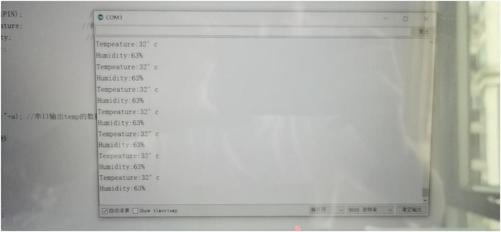
Serial.print("Tempeature:"); //Print out the Temperature:
Serial.print(tem); //Print temperature results
Serial.println("°c");
Serial.print("Humidity:"); //Print out Humidity:
Serial.print(hum); //Print out humidity results
Serial.println("%"); //Print out%
Serial.println("");
delay(500); //500 ms delay
}
Difficulties encountered
- Ams1117-5.0v will reduce the voltage, and dc005 will be less than 5V when powered by the wrong adapter(I measured it myself with a multimeter)It is better to use a 7-12V power adapter.
2.Ams1117-5.0v chip can be removed if you use dc002, or when power adapter is 5V, the chip can also be removed. - When drawing the schematic diagram library and package diagram library, the schematic pin must correspond to the component pin in the package diagram library. On this basis, it should correspond to the package pin of the actual component.(If you don't do this, the wiring of the designed circuit will go wrong)