Remote control desk lamp based on ESP8266
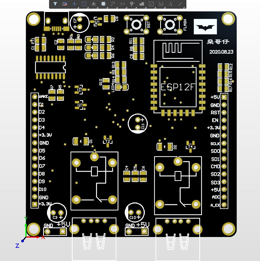
Hardware
micro USB
USB JACKS
relay
Some of resistance and capacitance
ESP8266-12F
CH340C
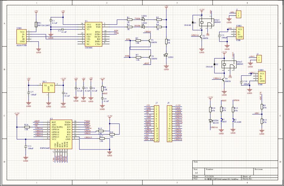
Hardware circuit
USB to UART one button download circuit
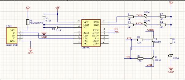
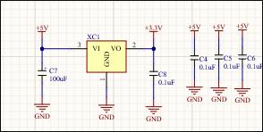
5V to 3.3V circuit (voltage reduction, power supply)
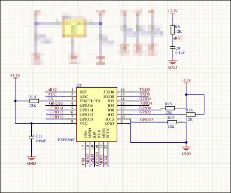
Esp8266-12f main control circuit
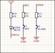
Key circuit
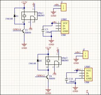
Relay circuit
In order to supply sufficient power to USB and avoid the stroboscopic light due to insufficient power supply, a capacitor is added and used to charge and discharge the capacitor to provide sufficient voltage (this is my personal idea. I don't know whether it is correct or not. It can only be tested in practice. Readers are also welcome to criticize and correct).
General circuit schematic diagram
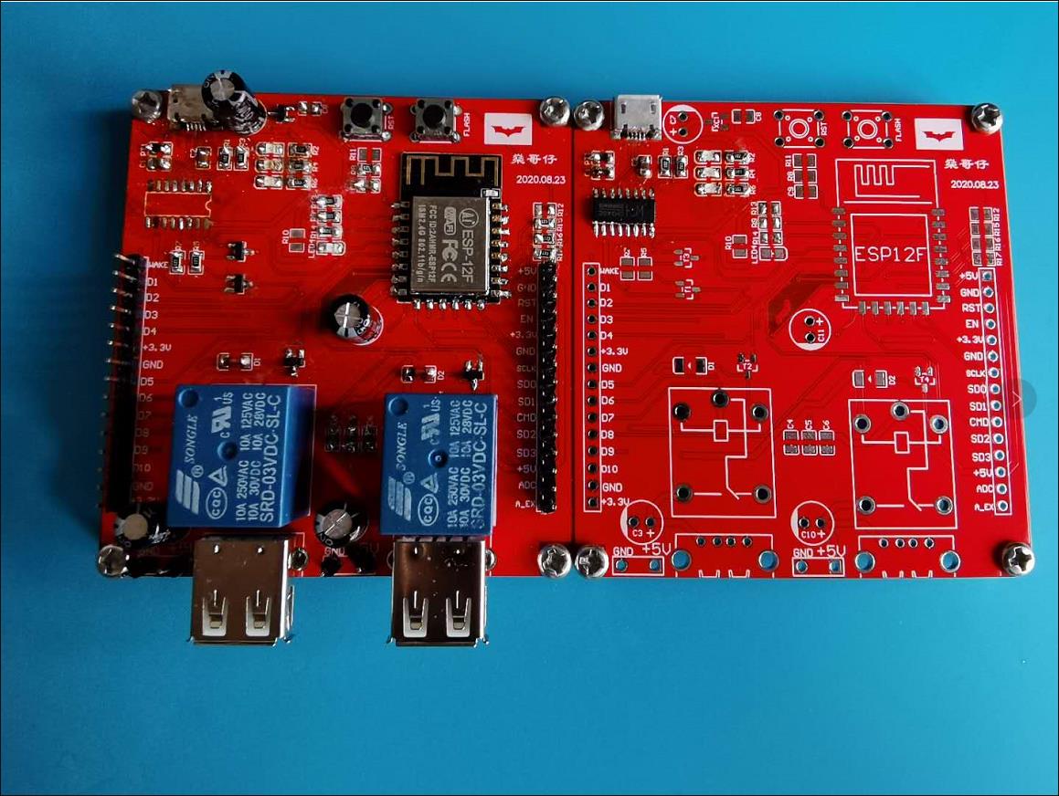
2020.8.28 Challenge part
When the board was welded, the first board was found to have a problem with the chip of ch340c after all the welding was completed. In the morning, the burning circuit ch340c was welded separately. The burning circuit in the new version is no problem, and the computer can recognize it successfully
Because they were too confident and didn't buy more components, it was difficult to check where there were errors in the first board, and they didn't check the schematic diagram well. Buying fewer components resulted in not having to weld three resistors. Although there was a minimum system, the downloaded firmware esp12f showed a very strange state of flashing all the time, but didn't run normally.
For more analysis, you can watch the video shared synchronously by BiliBili
BiliBili synchronized analysis video
2020.8.31 Control desk lamp successfully
Here is the video in bilibili.
The board designed by myself can theoretically control all devices powered by USB 5V.
Hardware code part
1. Download firmware for esp8266-12f first(You can download AT firmware first, and then overwrite and download nodemcu firmware to avoid errors)
- Then write code. You can use esplorer to write code with Lua, or use arduinoIDE to write code in C language. I use C language more and use arduinoIDE more, so I choose arduinoIDE.
Code idea: first connect to WiFi, after that connect to the Internet, and then connect to IOT platform(Here I use BIGIOIT platform to conduct intranet penetration, so that the information sent by the external network can be received). Then write the control code(There is a demo in BIGIOT, so it's easy to modify the demo then to achieve what I need.)
/*
This file needs to be supported by Arduino esp8266 development environment. For environment construction, you can see in: http://www.bigiot.net/talk/237.html

This program can be used to control two relays
Esp8266 burns into this program directly and uses the high and low electric frequency control optocoupler relay to control the electric lamp
By default, my relay is turned on at high power frequency, so it is initialized to low level during initialization. Play turns on d5 and stop turns off the light on D5.ESP8266 as a prompt light .
Code based :https://github.com/bigiot/bigiotArduino/blob/master/examples/ESP8266/kaiguan/kaiguan.ino
Adjust the code on. This code can be directly burned into nodemcu module. I hope it will be helpful for you to share the code (2020.9.7)
    此文件需安装Arduino esp8266开发环境支持,环境搭建参见:http://www.bigiot.net/talk/237.html
    本程序可以用来控制两路继电器
    ESP8266烧入此程序直接,使用高低电频控制光耦继电器来控制电灯
    我的继电器默认高电频开启,所以在初始化时都初始化为低电平,play开启D5,stop关闭D5.ESP8266上的灯作为提示灯
    代码基于https://github.com/bigiot/bigiotArduino/blob/master/examples/ESP8266/kaiguan/kaiguan.ino
    上的代码进行调整,此代码可以直接烧入到nodemcu模块,分享代码希望对大家有帮助(2020.9.7)
*/

#include <ESP8266WiFi.h>
#include <aJSON.h>

//=============  It must be modified here============
String DEVICEID="***"; // Your equipment number   ==
String  APIKEY = "***"; // Device password==//BIGIOT information
//=======================================
unsigned long lastCheckInTime = 0; //Record the last check-in time
const unsigned long postingInterval = 40000; // Report to the server every 40 seconds

const char* ssid     = "***";//Wifi name
const char* password = "***";//Wifi password

const char* host = "www.bigiot.net";
const int httpPort = 8181;

int ELed=D4;

int SW=D5;
int SW1=D6;
//int arr_len = sizeof(pins)/sizeof(pins[0]);

void setup() {
  Serial.begin(115200);
  delay(1000);

  WiFi.begin(ssid, password);
  //The default output turns off the electrical frequency
  pinMode(ELed,OUTPUT);
  pinMode(SW,OUTPUT);
  pinMode(SW1,OUTPUT);
  digitalWrite(ELed,HIGH);
  digitalWrite(SW,LOW);
  digitalWrite(SW1,LOW);


}

WiFiClient client;

void loop() {

  while (WiFi.status() != WL_CONNECTED) {
    delay(1000);
    Serial.print(".");
  }

  // Use WiFiClient class to create TCP connections
  if (!client.connected()) {
    if (!client.connect(host, httpPort)) {
      Serial.println("connection failed");
      delay(5000);
      return;
    }
  }

  if(millis() - lastCheckInTime > postingInterval || lastCheckInTime==0) {
    checkIn();
  }

  // Read all the lines of the reply from server and print them to Serial
  if (client.available()) {
    String inputString = client.readStringUntil('\n');
    inputString.trim();
    Serial.println(inputString);
    int len = inputString.length()+1;
    if(inputString.startsWith("{") && inputString.endsWith("}")){
      char jsonString[len];
      inputString.toCharArray(jsonString,len);
      aJsonObject *msg = aJson.parse(jsonString);
      processMessage(msg);
      aJson.deleteItem(msg);
    }
  }
}

void processMessage(aJsonObject *msg){
  aJsonObject* method = aJson.getObjectItem(msg, "M");
  aJsonObject* content = aJson.getObjectItem(msg, "C");
  aJsonObject* client_id = aJson.getObjectItem(msg, "ID");
  if (!method) {
    return;
  }
    String M = method->valuestring;
    if(M == "say"){
      String C = content->valuestring;
      String F_C_ID = client_id->valuestring;
      if(C == "sw1"){

        digitalWrite(ELed,LOW); //The light on ESP8266 is on
        digitalWrite(SW,HIGH);//D5 port is powered on
        sayToClient(F_C_ID,"LED All on!");
      }else if(C == "stop1"){

        digitalWrite(ELed,HIGH);//The light on ESP8266 is off
        digitalWrite(SW,LOW);//D5 port is powered off
        sayToClient(F_C_ID,"LED All off!"); // You  can see this hint in Bigiot
      }else if(C=="sw2"){
         digitalWrite(ELed,LOW);
        digitalWrite(SW1,HIGH);//D6 port is powered on
        sayToClient(F_C_ID,"SW2 ON!");
        }else if(C=="stop2"){
         digitalWrite(ELed,HIGH);
        digitalWrite(SW1,LOW);//D6 port is powered off
        sayToClient(F_C_ID,"SW2 OFF!");
        }


    }
}

void checkIn() {
    String msg = "{\"M\":\"checkin\",\"ID\":\"" + DEVICEID + "\",\"K\":\"" + APIKEY + "\"}\n";
    client.print(msg);
    lastCheckInTime = millis();
}

void sayToClient(String client_id, String content){
  String msg = "{\"M\":\"say\",\"ID\":\"" + client_id + "\",\"C\":\"" + content + "\"}\n";
  client.print(msg);
  lastCheckInTime = millis();
}
control software
Develop an app yourself or use the app provided by bigiot
Here I use the app developed by Hbuilderx, 5 + app. In short, it is a website app.
Reference code section:
//2020.9.15 update
<!DOCTYPE html>
<html >
<head >
<meta charset="utf-8">
<meta name="viewport" content="width=device-width,initial-scale=1,minimum-scale=1,maximum-scale=1,user-scalable=no" />
<title></title>
<script src="js/mui.min.js"></script>
<link rel="stylesheet" type="text/css" href="css/1.css"/>
<link href="css/mui.min.css" rel="stylesheet"/>
<script type="text/javascript" charset="utf-8">
mui.init();
</script>
</head>
<body>
<div class="abg">//Here class is a CSS style background picture written by myself.
<br>
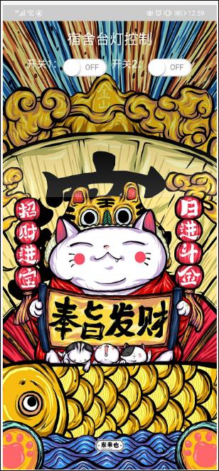
<div style="margin: auto;text-align: center;font-size: x-large;color: white;font:;"><label>宿舍台灯控制</label></div>
<br>
<div class="bod">
<div style="display: flex;color: white;"><label>开关1:</label>
<div class="mui-switch " id="mySwitch">
<div class="mui-switch-handle"></div>
</div>
<div style="display: flex; color: white;"><label> 开关2:</label>
<div class="mui-switch " id="mySwitch1">
<div class="mui-switch-handle"></div>
</div>
</div>
</div>
</div>
<script type="text/javascript">
var ws = new WebSocket("ws://www.bigiot.net:8383");
//var lb = document.getElementById("lb2")
ws.onopen = function() {
mui.toast("连接成功")//The software interface shows that the connection is successful
};
ws.onmessage = function(evt) {
var received_msg = evt.data;
//lb.innerText = received_msg
console.log(received_msg);
var obj = JSON.parse(received_msg)
if (obj.M == "WELCOME TO BIGIOT") {
ws.send('{"M":"checkin","ID":"设备ID","K":"APIKEY"}')//Send connection device
}
if(obj.M=="checkinok"){
mui.toast("服务器连接成功!可以进行控制")//Here is to judge whether BIGIOT has returned successful connection information
}
if (obj.M == "ping") //Determine whether the heartbeat packet is received
{
ws.send('{"M":"beat"}') //Send heartbeat packet data
}
};
document.getElementById("mySwitch").addEventListener("toggle", function(event) {
if (event.detail.isActive) {
mui.toast("打开开关1")
console.log("你启动了开关");
ws.send('{"M": "say","ID": "D+设备ID","C": "sw1","SIGN": "xx3"}')//D+设备ID,D代表设备。D+ID代表要发送信息到我们的esp8266设备
} else {
mui.toast("关闭开关1")
ws.send('{"M": "say","ID": "D+设备ID","C": "stop1","SIGN": "xx3"}')//这里发送的命令要跟ESP8266的判断的命令相匹配才会产生效果
console.log("你关闭了开关");
}
})
document.getElementById("mySwitch1").addEventListener("toggle", function(event) {
if (event.detail.isActive) {
mui.toast("打开开关2")
console.log("你启动了开关");
ws.send('{"M": "say","ID": "D+设备ID","C": "sw2","SIGN": "xx3"}')
} else {
mui.toast("关闭开关2")
ws.send('{"M": "say","ID": "D+设备ID","C": "stop2","SIGN": "xx3"}')
console.log("你关闭了开关");
}
})
</script>
</body>
</html>
Finally, the software interface is attached
The file is open source(2020.9.15),Gitee download address: https://gitee.com/riddler11/esp8266-control-desk-lamp/tree/master/
(2020.9.21)When applied to control desk lamps, some lamps will have stroboscopic problems. The preliminary analysis is that the internal components will divide the voltage and fail to reach the rated voltage, resulting in failure to work normally. It is necessary to analyze and calculate the circuit to solve this problem.