Wireless transmission of RFID identification information to server based on ESP8266.(基于ESP8266无线传输射频识别信息传输到服务器)
This is project I did a long time ago. Because of this project, I learn a lot of things. (Not only academically, but also the attitude of dealing with people.)
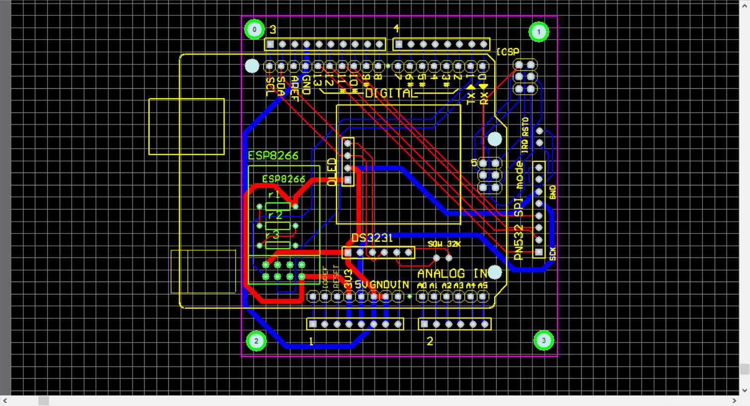
First, look back the board I designed in the past.
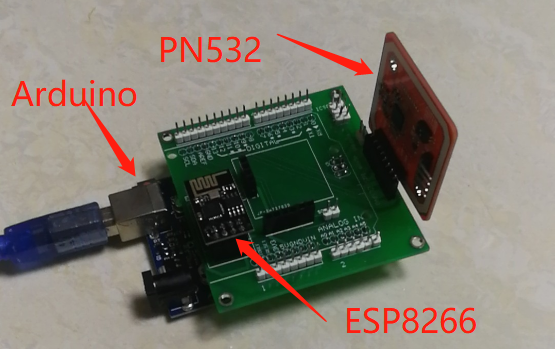
As we all know practice makes prefect. This is the design when I just learned how to use AD software. Integrated by three modules. Arduino uno, ESP8266 and PN532.
I use ESP8266 to wirelessly transmit the information received by PN532.
About ESP8266
It has three modes
- STA (station)
- AP (Access Point)
- STA、AP Both
The technical part adopts STA mode in this project. Arduino sends AT instruction to initialize the module.
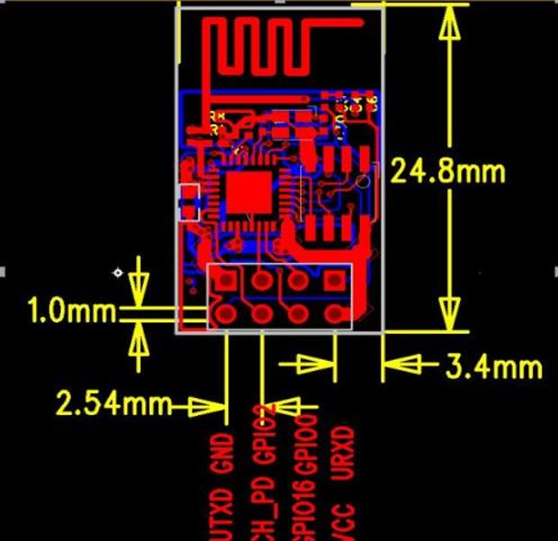
But how to connect with the module.
My method is as follows.
| Arduino | connect | ESP8266 |
|---|---|---|
| 3.3V | <—> | VCC |
| GND | <—> | GND |
| TXD | <—> | RXD |
| RXD | <—> | TXD |
| 3.3V | <—> | CH _PD(I added pull-up resistor 1.5K*3. Add a pull resistor about 10K on the internet.) |
On transmission communication of several modes of PN532.
As you can see, there are three modes to transmit messages.
HSU、SPI、I2C.
Used with Arduino UNO:
In HSU mode, the serial port monitor will have no information (inconvenient for debugging).
I have never used I2C mode. So I use SPI mode to implementation.
How to turn on SPI mode? Switch channel1: OFF, channel2: ON.
This is the note I wrote before.
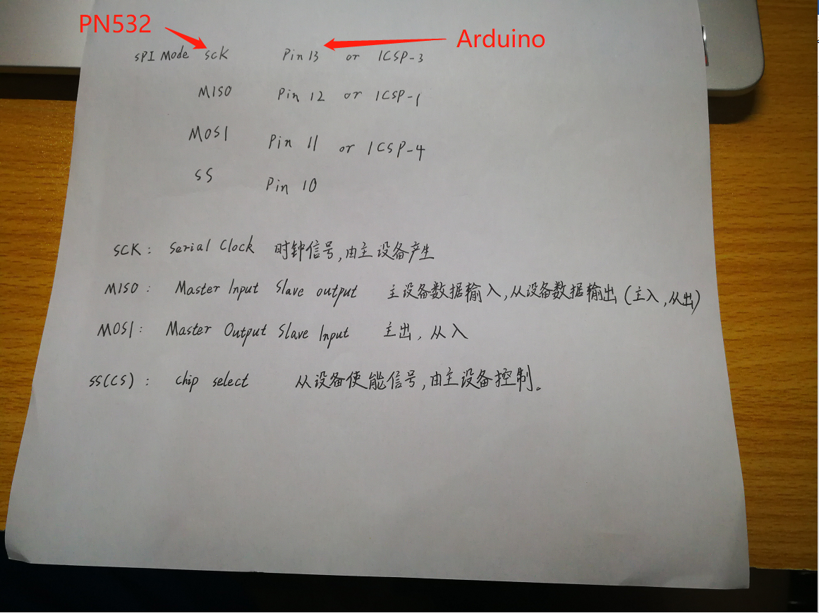
Module connection
| Arduino | connect | PN532(SPI mode) |
|---|---|---|
| Pin13 or ICSP-3 | <—> | SCK |
| Pin12 or ICSP-1 | <—> | MISO |
| Pin12 or ICSP-4 | <—> | MOSI |
| Pin10 | <—> | SS |
| PN532 Pin | Description of pin |
|---|---|
| SCK: | Serial Clock |
| MISO: | Master Input Slave Output |
| MOSI: | Master Output Slave Input |
| SS(CS): | Chip Select |
Oh my god. What a terrible design. (This is what I made at that time.)
Hardware running process.
- Arduino power-on startup procedure.
- Initialize the wireless module, connect the wireless module with the preset WiFi, and then connect the server written in Java through TCP protoco
- PN532 starts and waits for the card to be read.
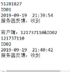
- When there is a card on it, send the card ID to the server.
Software part:
Database design, Server based on Java.
Java server code:
It is divided into three parts: Server part, multithreading part, and display database part (for the convenience of connecting with Android in the back).
Implementation effect
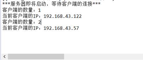
Video in bilibili.